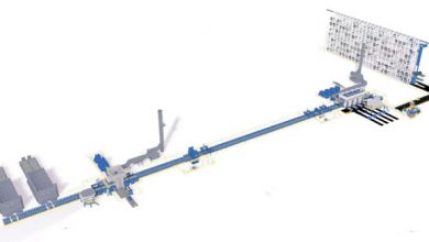
Challenges in Aluminum Ingot Sawing Operations
Band sawing aluminum ingots typically presents three major categories of challenges: durability issues at the tooth tips, fatigue and deformation of the blade backing, and problems associated with the sawing process itself. This article explains the mechanisms behind each issue and provides solutions to help operators—regardless of experience level—use band saws more effectively.
Understanding the root causes of common sawing issues and how to quickly resolve them benefits both new and experienced operators. Although sawing issues may vary depending on material size, shape, and other characteristics, general guiding principles can still serve as strong references.
Challenges of Tooth Tip Durability
1) Tooth breakage (“tooth pull-out”)
-
Improper blade break‑in
Improper break-in can cause teeth to chip, which shortens blade life and may lead to tooth breakage. Always follow the band‑blade supplier’s recommended break‑in procedure. -
Line speed too low
If the linear speed is set too low for the material, the feed per tooth becomes excessive (to maintain sawing efficiency), overloading the welds and ultimately causing tooth breakage. -
Excessive feed downward pressure
Reduce downward feed pressure to avoid overfeeding and tooth pull‑out. -
Blade binds in the kerf during sawing
If a broken tooth tip gets stuck in the kerf, do not install a new blade and resume sawing at that same position. Residual tooth fragments can damage the new blade’s teeth. The best approach is to start a fresh kerf—or if you must saw in the same location, flip the workpiece and start from the opposite side. -
Incorrect coolant mix or flow
Proper coolant flow and mix are essential for sawing almost all materials, providing cooling and lubrication. Incorrect application generates excessive heat, reducing blade life and causing tooth breakage. -
Hard spots or case‑hardened materials
Materials with hard spots or case hardening are prone to tooth pull‑out. Use reduced line speed and feed to overcome this tendency—but bear in mind these materials are more susceptible to tooth breakage. -
Wrong tooth pitch
An overly coarse tooth pitch subjects each tooth to excessive impact, causing pull‑out. -
Workpiece movement in the vise
Even slight movement—e.g. in bundle sawing—can lead to tooth breakage. Use secure vices or specialized clamps to immobilize the material. -
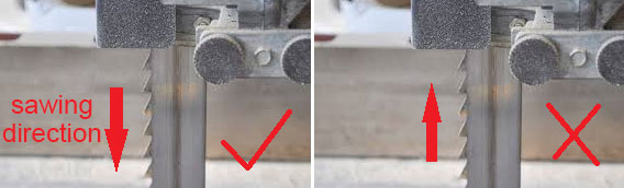
Blade installed in the wrong direction
If the band saw blade is mounted backward, the tooth movement becomes incorrect when the machine starts. Solution: remove, reverse, and reinstall the blade properly.
2) Premature tooth dulling
Most causes overlap with those listed above. In addition, when sawing work‑hardening materials—such as stainless steel, nickel alloys, and cold‑work mold steel—each tooth must fully engage the material. If some teeth do not cut, they rub on the workpiece surface (similar to a knife edge skidding across a whetstone), causing early dulling. The remedy is to increase downward feed pressure or feed rate.
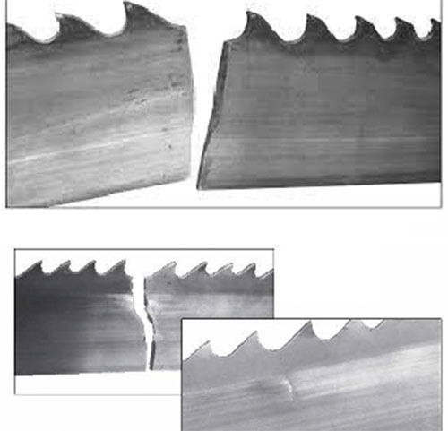
3) Back‑face relief side tooth breakage
Back‑face tooth breakage indicates the workpiece is moving in the vise. Inspect and adjust the vise, and use specialized clamps. Workpieces that rotate or vibrate during sawing often cause chips to strike the back relief face and break teeth.
Challenges Related to Blade Backing Life
1) Wear or burrs on the backing edge
-
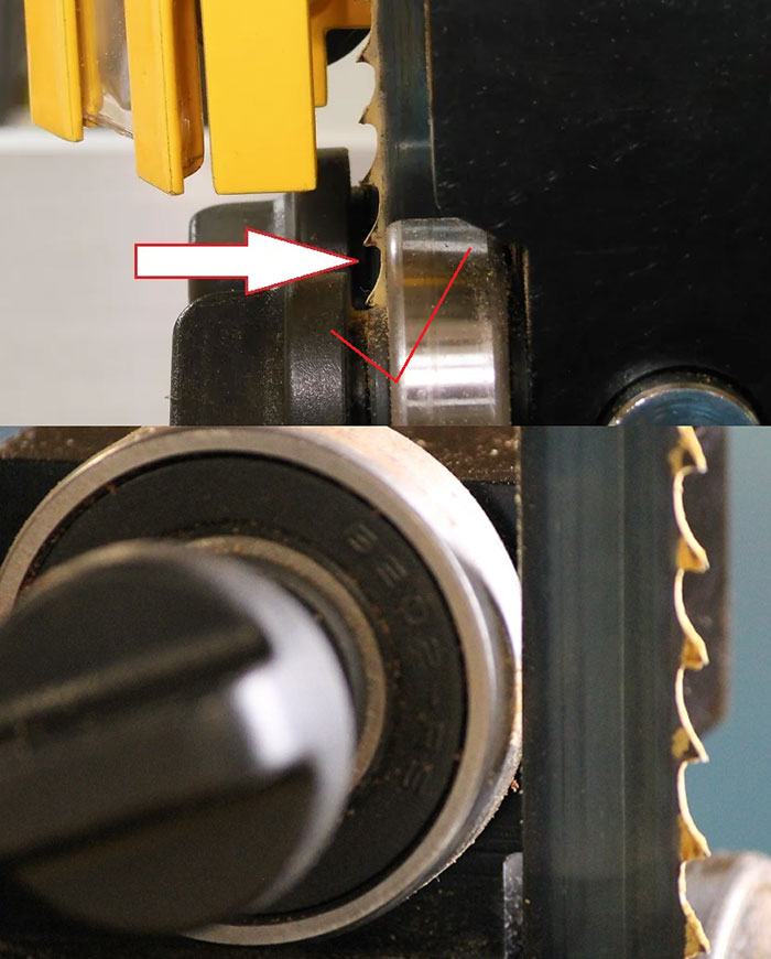
Worn or damaged backing guide wheels
The guide wheel surfaces should be smooth, free of grooves, and rotate freely, as the blade backing runs against them to transmit feed force during sawing. -
Excessive guide wheel preload
Proper preload of the backing guide wheels is crucial. If set to push the blade, both guide and blade wear will accelerate. -
Low blade tension
Insufficient tension causes the blade to flex between guide arms, leading to cracking along the backing edge. -
Guide arms spaced too far apart
Like low tension, wide guide spacing allows flexing that eventually cracks the backing edge. Adjust arms closer to the workpiece. -
High feed rate or pressure
Lower feed rate or pressure to prevent excessive wear on the backing edge. -
Blade friction against wheel flanges
Ensure the blade backing does not touch the saw wheel flanges. Adjust the guides to keep the edge close but flange‑free. Contact with the flange can form sharp edges or burrs, which lead to backing failure.
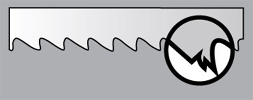
2) Backing edge fracture
-
Excessive blade tension
Straight fatigue cracks occur under over‑tension. Most production saws require 190–220 MPa; always verify tension with a gauge. -
Wheel diameter too small for blade width
Narrow tires lack proper support, resulting in unsupported bending and irregular fractures. -
Worn guide blocks or wheels
Replace worn or damaged blocks to prevent cracks. Curved fractures often point to side‑guide damage. -
Blade rubbing wheel flanges or overly tight side guides
These conditions cause fractures and tooth‑pitch rollback.
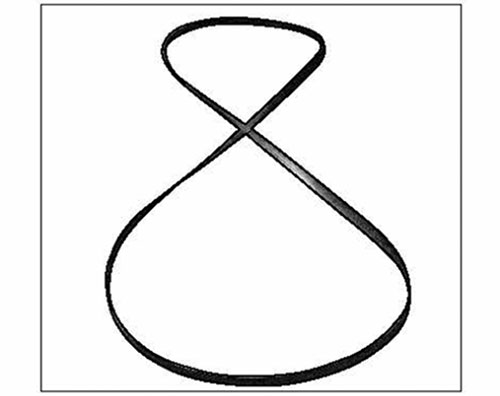
3) Blade twisting and deformation
-
Backing jams in the kerf
Materials with high internal stress (e.g. forged titanium, nickel alloys) can pinch the blade backing during sawing. Fix this by inserting a wedge into the kerf or switching to a coarser‑tooth blade to widen the kerf, or reduce feed rate for slight binding. -
Workpiece loose in vise
See solutions above for securing the workpiece. -
Guide arms spaced too far apart
Adjust guide arms closer to the material. -
Low tension
Without proper tension, the blade bends and twists, causing breakage and crooked sawing.
Sawing‑Related Problems
1) Tapered cuts
-
Excessive feed rate
Blade speed, feed pressure, and feed rate must be balanced for the material—poor parameter settings often cause tapered cuts. -
Low blade tension
Results in insufficient blade stiffness and crooked sawing. -
Tooth‑pitch rollback or damage
Hard materials, poor blade tracking, or worn guides can cause tooth‑pitch issues, leading to taper. -
Loose or widely spaced guides
Similar to tension issues: inadequate support leads to crooked cuts.
2) Tooth gumming / chip welding

-
Worn brush
Though brushes do not directly cause gumming, a malfunctioning brush allows chips to accumulate in gullets, generating heat and causing gumming. Maintain or replace brushes as needed. -
Incorrect or insufficient coolant
Coolant is critical for lubrication and cooling. Improper mix or flow causes overheating and chip welding. Verify flow rate and coolant type. -
High feed rate or sawing speed
Generates heat that promotes chip welding. Follow supplier‑recommended parameters.
3) Unexpected blade breakage due to saw settings
-
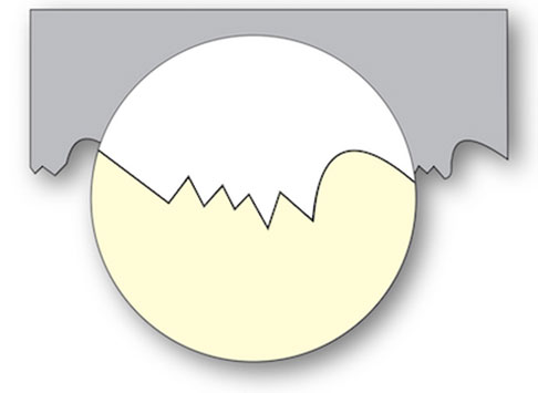
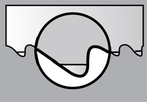
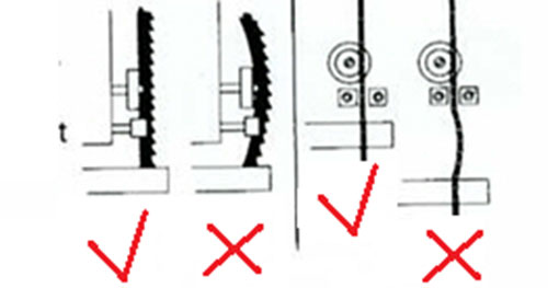
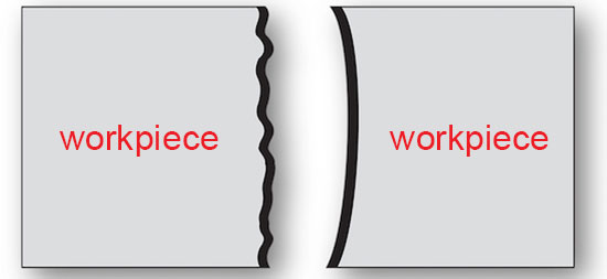
Incorrect feed start position
If the feed starts within the material curve, the blade may abruptly impact the workpiece, breaking teeth. Adjust feed start clearances. -
Uncontrolled head drop
On horizontal or dual‑pivot saws, hydraulic failure can cause the head to drop into the workpiece, damaging the blade. Ensure no cylinder leaks.
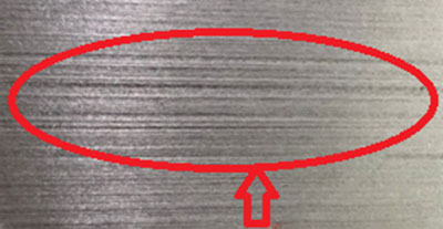
4) Poor surface finish
- Dull or damaged teeth
These alter tooth geometry and spacing, creating washboard‑type saw marks. Difficult materials or high‑speed aluminum sawing may also produce irregular sounds. Replace the blade.
- Incorrect feed rate or sawing speed
These are critical for surface quality and blade life. Low speed allows chip buildup, causing blade wander; high feed overloads the blade. - Lack of blade support
Tighten and adjust guide arms. Loose guides allow wandering and compromise straight sawing. - Low blade tension
Causes lateral wandering—maintain tension per supplier specs. - Wrong tooth pitch
Too coarse pitch leads to chip accumulation, causing wandering. Select pitch per blade manual.
5) Backing wear and tooth‑pitch rollback

-
Teeth cut into side guide
Sharp wear on side guides often indicates a worn top backing guide wheel—inspect and replace if needed. -
Side guide overly tight
Side guides should have zero clearance but not be overtightened—adjust spacing appropriately. -
Teeth pressed against wheel flange
Proper tracking keeps backing edge close without tooth contact. Replace worn wheels if needed.
6) Challenges with hard‑to‑saw materials and high‑speed operations
-
Difficult materials
Materials like high‑alloy stainless steel, high‑temperature alloys, titanium, and large mold steels can stall blades or saw few parts. For hardened crankshafts (~50 HRC), zero or negative‑rake carbide‑tipped blades are recommended. Super‑alloys need rigid saws and specialized blades—e.g. carbide for nickel‑base alloys; stainless often uses bi‑metal blades with variable pitch for chip evacuation. -
High‑speed aluminum sawing
High‑speed sawing of materials like aluminum requires blades with excellent weld quality and blade integrity (e.g. TCB‑PRO series), and meticulous saw maintenance.