The auger extruder is widely used all over the world. Metals producers use them to agglomerate and pelletize metallurgical by-products for engineered feedstock. Brick, block and tile manufacturers use them to shape clays and shales.
Stiff extrusion is ideal for a wide range of plastic and non-plastic materials, requiring minimal added water. The machine from Maxton agglomerates and extrudes a shaped product with superior strength and structural integrity when output from the die.
The processed raw materials are sent to the feeding section of the upper mixing part through a conveyor, and in the feeding section, appropriate amount of water can be added to the raw materials to adjust the briquetting moisture.
With the rotation of the stirring shaft, the mixing knife continuously mixes and homogenizes the raw materials, and continuously pushes the raw materials to the sealing extrusion section. In the sealing extrusion section, there are a pair of spiral sealing reamers that rotate in opposite directions continuously. Thus sent raw materials are extruded and kneaded, and the material is finally extruded into dense sticks through the material sealing grate plate and continuously squeezed into the vacuum box, and the dense sticks are formed on the population of the vacuum box Vacuum mud seal to ensure the required vacuum degree in the vacuum box.
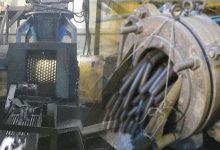
When the raw material falls from the vacuum box into the lower receiving box, the air in the vacuum box and the stick is sucked out by the vacuum pump through the vacuum suction pipe on the top of the vacuum box to realize the vacuum treatment. The material then falling into the lower receiving box and forcibly pressed into the lower extrusion reamer through a pair of pressing plates with opposite rotation directions. With the rotation of the reamer shaft and the diameter and pitch of the reamer itself, the structural characteristics make the material gradually compacted during the forward conveying process, and finally extruded into a briquette or brick with the desired shape and section through the machine head and the forming outlet.
The compressed air provides pressure air source for the upper and lower axial pneumatic clutches, and the automatic clutch of the pneumatic clutches is controlled by the electromagnetic cut-off valve, so that the upper and lower stages can be started and stopped at any time during the operation of the equipment.
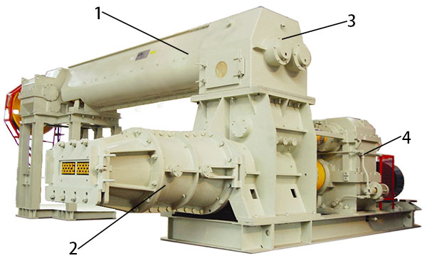
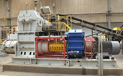
1. Upper mixing part 2. Lower extrusion part 3. Vacuum system 4. Forced lubrication system
This extrusion equipment is composed of five parts: the upper mixing part, the lower extrusion part, the vacuum system, the forced lubrication system and the pneumatic system.
Mainly composed of transmission motor, pneumatic clutch, reducer, gear box, mixing tank, sealing cylinder, sealing reamer, material sealing grate plate, vacuum box and other components.
The mixing tank is equipped with a water spreading pipeline to adjust the moisture of the raw materials.
The top of the vacuum box is equipped with a vacuum exhaust pipe, a lighting lamp and a vacuum gauge. The sealing reamer installed on the mixing shaft is a split structure, which is convenient for maintenance and disassembly.
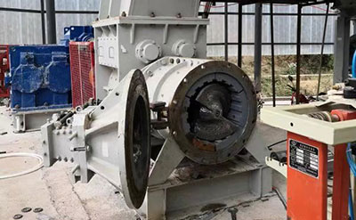
It is mainly composed of transmission motor, pneumatic clutch, reducer, gear box, receiving box, mud pressing plate, reamer shaft, reamer, split clay cylinder, machine head and other components. A pressure gauge is installed on the machine head to observe the molding extrusion pressure.
It is composed of oil-sealed slide valve pump, air filter, exhaust pipeline, pipe joints, valves, etc.
It is composed of gear oil pump device, oil filter, oil separator and so on. Its function is to forcibly lubricate the reamer shaft bearing, the mud plate shaft bearing and the gears in the gearbox to ensure long-term and reliable operation of the equipment.
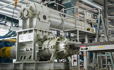
Extruder with deairing double shaft mixer  Extruder with deairing single shaft mixer
  Extruder with deairing pug sealer Single extruder
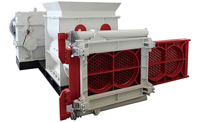
 (with easy die changer)
| Model | Auger diameter (mm) | Pressure (MPa) | Capacity (m3/h) | Power (kW) |
| JKY45 | 450 | 4.0 | 40-60 | 55/110/15 |
| JKY50 | 500 | 4.0 | 55-75 | 55/132/15 |
| JKY55 | 550 | 4.0 | 70-90 | 75/160/15 |
| JKY60 | 600 | 4.0 | 80-100 | 75/200/22 |
| JKY70 | 700 | 4.0 | 90-110 | 90/250/22 |
| JKY75 | 750 | 4.0 | 100-120 | 90/285/22 |


In briquetting, the binder is often the unsung hero. Whether you’re compacting…
Why Make Cold Iron Ore and By-product Briquettes With the shortage of…
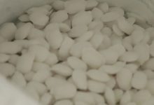
What is water softnter salt briquette Water softener salt briquette, also known…
What is coke fine Coke fine refers to the small-sized particles or…
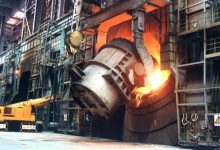
Why Deoxidation in Steelmaking Deoxidation plays a dual role in the steelmaking…
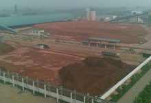
What is red mud Around 1888, Austrian chemist Carl Josef Bayer developed…