History of Midrex Furnace
The Surface Combustion Corporation of the United States began researching the direct reduction process using natural gas in 1936. After extensive experimentation, it wasn’t until 1966 that significant breakthroughs were made in two key technologies: natural gas reforming to produce reducing gas and the counter-current heat exchange reduction shaft furnace.
In 1966, a test unit with a diameter of 450mm and a daily production of 1.5 tons was established at the Oregon Steel Plant. Following successful trials, the MIDREX-ROSS Corporation in the United States, after multiple experiments and modifications, constructed and commissioned two sets of natural gas shaft furnace direct reduction equipment (2×200,000 tons/year) in 1967. In 1969, two production units with an annual output of 150,000 tons of DRI and a diameter of 3.7 meters were built at the plant. By 1971, the company had established a 400,000 tons/year direct reduced iron production plant for Korf Company in West Germany, thereby forming a new process of direct reduction-electric furnace-continuous casting.
This new process garnered significant attention and became the fastest-growing method in direct reduction.
Currently, there are MIDREX process production facilities with a single annual capacity of 2 million tons. To date, the MIDREX process still holds a pivotal position in direct reduction ironmaking technology. Statistics show that about 67% of the total DRI production capacity is produced using MIDREX shaft furnaces, another main shaft is HYL.
Process Principle and Flow
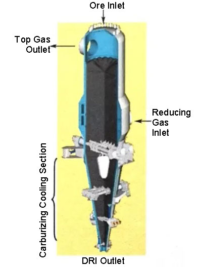
The MIDREX process is suitable for processing low-sulfur ores (S<0.01%). When natural gas is used as the raw material for reducing gas, approximately one-third of the CO2 in the dedusted and dehydrated furnace top gas is used as a reforming agent, mixed with fresh natural gas in stoichiometric proportions, and then fed into the reforming furnace equipped with nickel catalyst tubes. In the reforming furnace, the raw gas undergoes catalytic reforming through a nickel-based catalyst in the heating furnace, reacting at 900-950°C to completely decompose methane, achieving an H2/CO ratio of 1.5-1.8 in the gas, and obtaining reducing gas with (H2+CO) >90%. The reforming reaction is CO2+CH4=2CO+2H2. The reforming gas temperature (850-930°C) fits the requirements of the shaft furnace reduction process and can be directly used. The reduction shaft furnace is divided into two parts: the upper part for preheating and reduction, and the lower part for cooling. The raw material enters the furnace through a feed pipe, is preheated by hot reducing gas, and undergoes reduction reactions. The reducing gas enters the shaft furnace at 850-930°C, 0.1-0.3 MPa pressure, and 1800m³/h flow rate. The hot reducing gas, containing about 95% (H2+CO), is fed into the middle peripheral inlet of the shaft furnace, and the gas exhausted after the reduction reaction exits from the top of the furnace, known as top gas.
The typical process of the MIDREX method involves controlling the descent speed of the raw material in the shaft furnace by the discharge mechanism at the furnace bottom. After entering the furnace, the raw material descends by gravity to the bottom of the shaft furnace, where it is discharged as the finished product. The reduction zone height is about 9 meters, with a retention time of 5-6 hours, equating to a descent rate of 30mm per minute. The raw material is preheated and reduced by contacting the upward-flowing furnace gas in the preheating and reduction zones. The raw material is reduced to metallic iron in the solid state, with a metallization rate of 92% and carbon content of 0.5-2.5%, which can be controlled as required. The top gas, after undergoing reduction reactions in the shaft furnace, exits at 400-450°C, 0.05-0.20 MPa, and contains 6000mg/m³ of dust.
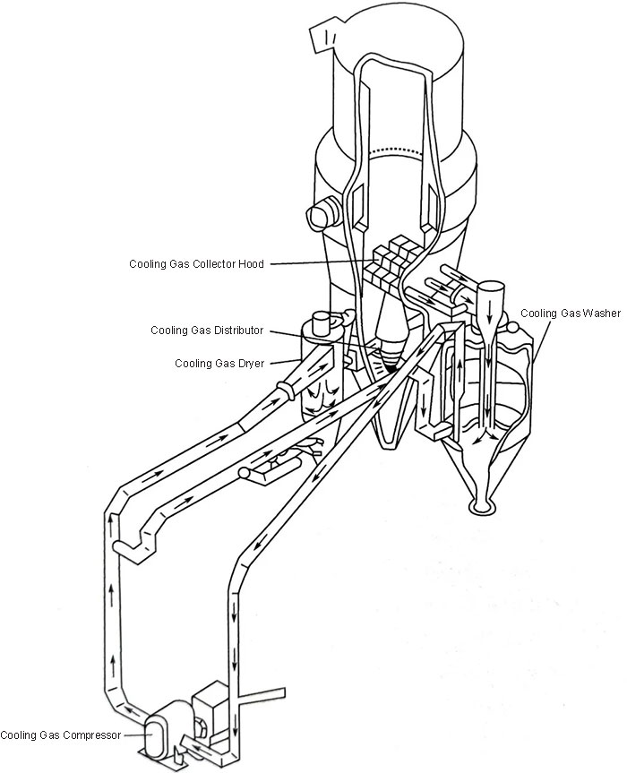
The reduced DRI is cooled to about 50°C in the cooling zone at the bottom of the shaft furnace by a separately circulating cooling gas. The cooling section is the most complex part of the furnace, consisting mainly of a cooling gas system, which includes a cooling gas washer, a cooling gas compressor, a cooling gas dryer, a cooling gas distributor, and a complex pipeline system. The cooling gas inlet temperature is below 40°C, pressure is 0.1-0.3 MPa, and the flow rate is controlled at approximately 1000m³/h. Its composition is similar to that of the top gas, but it contains a certain amount of CH4 for carburizing. The cooling gas temperature at the outlet of the shaft furnace is about 450°C, with a dust content of 6000mg/m³; after cooling and washing, the temperature drops to 35°C, the dust content to 4mg/m³, and the pressure is about 0.05 MPa. After pressurization, the gas can be recycled.
The shaft furnace uses gas sealing devices for both feeding and discharging, with a sealing gas pressure of 0.10-0.14 MPa and a flow rate of 1000-2000m³/h. The composition is CO2 14.5%, H2O 20.3%, N2 64.2%, O2 1%. The metallized product discharged from the shaft furnace (below 52°C) is conveyed to the iron grid screen by a belt conveyor (sampled and weighed on the belt) for screening. The bonded lumps on the screen are crushed and mixed with the finished product before entering the product warehouse. The MIDREX shaft furnace has rapidly developed worldwide and has become the most mature and largest direct reduction ironmaking method. Currently, most of the MIDREX natural gas-based shaft furnaces in production have a DRI capacity of 800,000-1,600,000 tons/year.
In 2019, MIDREX built two shaft furnaces in Algeria with the largest single annual capacity of 2.5 million tons of DRI, one of which is already in operation. The process gas pressure at the furnace inlet of the MIDREX shaft furnace is 0.15-0.40 MPa, and the inlet temperature is 840-900°C. The second-generation process uses a heat recovery exchanger to preheat combustion air and raw gas sequentially, making full use of the waste heat in the flue gas. The comprehensive energy utilization efficiency of the second-generation reformer MIDREX plant is about 6.3% higher than that of the first-generation plant. Due to its mature technology and high productivity, the MIDREX shaft furnace has been widely promoted and applied, with facilities having an annual capacity of tens of millions of tons.
MIDREX Raw Material Requirements
Since the establishment of the MIDREX shaft furnace in the late 1960s, it has developed rapidly and become the main production form of direct reduction metallurgy. Its features include compact equipment, full utilization of thermal energy, and high productivity, with a utilization coefficient of 9-12 tons per cubic meter of the reduction zone. However, the gas reforming equipment is very expensive and easily damaged, requiring strict control of the sulfur content in iron ore and gas. The MIDREX process is suitable for most lump ores and selected oxide pellets, with the following general requirements:
- Particle size: Oxide pellets or lump ore of about 10-30mm, with less than 5% below 5mm.
- Mechanical strength: The mechanical strength required for the shaft furnace direct reduction process is not as high as that for blast furnaces, but it must be sufficient to prevent the generation of large amounts of fines during transportation.
- Reducibility: Good reducibility is necessary to ensure high productivity in the direct reduction shaft furnace.
- Thermal shock resistance: Lump ore should have minimal thermal shock during the addition to the shaft furnace and the reduction process; otherwise, it will generate large amounts of fines, affecting the furnace’s productivity. For a standard MIDREX reduction plant, using easily spalling lump ore instead of high-quality pellets can reduce the shaft furnace’s output by 5-15%, increase fuel consumption by 2-4% per ton of reduced product, and increase electricity consumption by 10-15%.
- Chemical composition requirements for raw materials: For the MIDREX direct reduction process, the chemical composition of the raw materials is secondary, but it is crucial for subsequent steelmaking processes. Electric furnace smelting requires raw materials with an iron content >67%, SiO2 and Al2O3 total content ≤3%, (SiO2+Al2O3)/Fe ratio generally not exceeding 5%, S content ≤0.025%, P content ≤0.03%, Cu content ≤0.03%, TiO2 content ≤0.35%. To relax the sulfur content requirements for iron ore, the MIDREX process proposes an alternative production flow, using top gas as the cooling gas. The cooling gas undergoes desulfurization reactions with low-sulfur DRI in the cooling zone to reduce the sulfur content in the gas, with the reaction being H2S+Fe=FeS+H2.
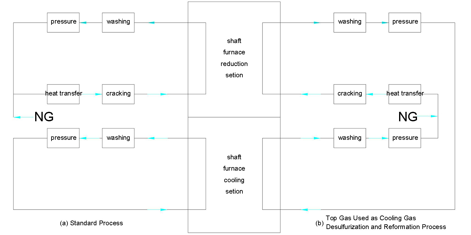
Although this process increases the sulfur content in DRI products, it does not exceed the standard limit. The desulfurized gas, mixed with fresh natural gas, is sent to the reformer for reformation. Since the sulfur content in the gas is reduced, the catalyst’s lifespan is extended. This process allows the use of iron ore with a sulfur content of 0.02%. If the sulfur content in iron ore or natural gas is high or fluctuates significantly, a gas desulfurization unit must be added to the process to protect the reformer catalyst from poisoning and failure, which would affect normal production.
MXCOL Coal Gasification Process
The MIDREX shaft furnace has also developed the MXCOL coal gasification process. Jindal Company in Orissa, India, built a shaft furnace using the Lurgi coal gasification process for the SPL MXCOL project, with a designed annual capacity of 1.9 million tons of direct reduced iron (DRI). Due to environmental issues with the Lurgi gasification process, the original plan to start production in 2008 was repeatedly postponed and has yet to commence normal production. When the HYL shaft furnace is connected to the Lurgi coal gasification process, the designed process gas input for the shaft furnace is 1800 m³, with a H2/CO ratio of 1.5, a temperature of 900°C, and a syngas consumption of 849 m³/t (DRI), equivalent to 9.25 GJ/t (DRI). The Lurgi furnace, which uses pressurized gasification technology, requires lump coal or briquette coal and produces syngas at 40°C and 2.75 MPa. Currently, there are over 200 industrial installations operating. The raw gas from the Lurgi furnace contains significant amounts of benzene and phenol water and coal tar, making the condensation and washing wastewater treatment system quite complex. The raw gas composition is H₂ 37%~39%, CO 17%~18%, CO₂ 32%, CH₄ 8%~10%, which, after processing, can be used as city gas and syngas.
The MIDREX coal gasification shaft furnace process includes the use of COREX 2000 melter gasifier to produce direct reduced iron with high CO content coal. Two MIDREX shaft furnaces in Angul, India, started production in 2014, and one in Saldanha, South Africa, started in 1999. These three shaft furnaces, with an annual capacity of 800,000 tons of DRI, use reduction gas with a H₂/CO ratio of about 0.3. Due to the high CO content in the gas, severe carbon deposition reactions can easily occur during heating to 400~750°C: 2CO = CO₂ + C. Carbon deposition not only severely clogs gas channels but also corrodes and damages gas pipelines. MIDREX employs a rapid heating method to avoid carbon deposition, purifying and reducing CO₂ to below 5%, then heating the gas to 400°C. Simultaneously, a combustion furnace burns liquefied petroleum gas (LPG) with oxygen to produce 1300°C incomplete combustion gas. The mixed gas, adjusted to 840°C, is used as the process gas input to the MIDREX shaft furnace to reduce pellet and fine ores, producing high-quality DRI as steelmaking furnace feedstock.
The reduction gas heating device consists of primary and secondary heating. The primary heating uses VPSA waste gas, MIDREX shaft furnace top gas, LPG, and compressed air, with LPG as a backup. When the primary heating temperature falls below the minimum, VPSA waste gas and MIDREX shaft furnace top gas are turned off, and only LPG and compressed air are used for rapid heating. The secondary heating uses reduction gas, LPG, and oxygen. The role of LPG in secondary heating is similar to primary heating. The cooling gas in the MIDREX shaft furnace cooling section consists of cooled reduction gas and LPG.
MIDREX’s requirements for coal-based syngas are shown in below table. In recent years, MIDREX has also been integrating direct reduction and coal gasification technologies. They have partnered with U-gas fluidized bed coal gasification technology suppliers to carry out EPC projects for coal gasification-based direct reduction shaft furnaces in China. For China’s coke oven gas resources, MIDREX has developed a purification and reformation thermal reaction system with Praxair, using syngas for the MIDREX process in the MXCOL process.
| Item | Unit | Feasible | Recommend |
| Gas quality (H2+CO/CO2+H2O) | times | >10 | CO2≥3 |
| H2/CO | times | ≥0.3 | 1-2 |
| Pressure | MPa | <0.5 | <0.5 |
| Sulfur Content (Volume Ratio) | PPM | about 100 | about 100 |
| Dust Content | mg/m3 | <10 | <10 |
| N2+Ar | % | <1 | <0.5 |
| Methane Content | % | <15 | 4-12% |
| Consumption | Gcal/t(DRI) | about 2.25 |
MIDREX H2 Process
The MIDREX H2 process uses 100% hydrogen as the reducing gas. The technical route evolves from the MIDREX NG process, which uses natural gas (NG) as the reducing gas, by gradually adding hydrogen. Depending on the hydrogen supply method, it can be divided into external hydrogen injection and electrolytic hydrogen supply. The externally generated gas is introduced into the conventional MIDREX production system without the need for a reformer, and the gas heating device heats the gas to the required temperature.
To control the furnace temperature and carburization, the actual hydrogen content in the reducing gas is about 90%, with the remainder being CO, CO₂, H₂O, and CH₄, introduced during furnace temperature control and DRI carburization with natural gas. Additionally, due to the water-gas reaction in the shaft furnace, CO₂ and CO in the reducing gas remain balanced, so a CO₂ removal device is unnecessary. It is estimated that producing one ton of DRI consumes about 550 m³ (standard) of hydrogen, plus an additional 250 m³ (standard) of H₂ as fuel for the reduction gas heater. Compared to the blast furnace process, this process can reduce CO₂ emissions by about 80%.

MIDREX Process Features
The MIDREX direct reduction shaft furnace has the following features:
- Countercurrent contact of materials and gas, resulting in high heat and mass transfer efficiency, and high operational and production rates.
- Recycling of top gas, leading to high energy utilization efficiency.
- Stable production without furnace adhesion issues, and no dead zones in the shaft furnace.
- Stable material flow and uniform gas flow distribution ensure a stable product with a high metallization rate.
- Product carbon content can be adjusted according to needs, improving steelmaking efficiency.
- The coal gasification system includes desulfurization, resulting in very low sulfur content in the product.
- No furnace hearth refractory erosion issues, with a furnace lifespan of over 10 years, and some plants operating for over 40 years.